
European Geologist Journal 51
Site appraisal in fractured rock media: coupling engineering geological mapping and geotechnical modelling
by Helder I. Chaminé*, Maria José Afonso, José Filinto Trigo, Liliana Freitas, Luís Ramos, and José Martins Carvalho
* Laboratory of Cartography and Applied Geology, School of Engineering (ISEP), Polytechnic of Porto, Portugal
Contact: hic@isep.ipp.pt
Abstract
Geotechnical surveys are based on collecting data from fieldwork and are a key element of rock-mass quality assessment in rock engineering. The lessons learned in several engineering projects underline the value of the accuracy of the basic geological and geotechnical data information related to the rock masses description and evaluation. An evaluation based on engineering geosciences, hydraulic and geotechnical features of rock masses involves combining parameters to derive quantitative geomechanical classifications for engineering design. In the present work, two selected sites are highlighted to demonstrate the importance of GIS mapping and models. Mapping and quantifying the on-site measurements’ information content and building a geo-database is vital for decision-making processes and risk assessment on sustainable engineering design with nature and hazards.
Cite as: Chaminé, Helder I., Afonso, Maria José, Filinto Trigo, José, Freitas, Liliana, Ramos, Luís, & Martins Carvalho, José. (2021). Site appraisal in fractured rock media: coupling engineering geological mapping and geotechnical modelling. European Geologist, 51. http://doi.org/10.5281/zenodo.4948771

This work is licensed under a Creative Commons Attribution 4.0 International License.
Introduction
Barton and Quadros (2015) argue the following:
“Anisotropy is everywhere. Isotropy is rare. Round stones are collectors’ items, and any almost cubic blocks are photographed, as they are the exception. The reasons for rock masses to frequently exhibit impressive degrees of anisotropy, with properties varying with direction of observation and measurement, are clearly their varied geological origins. Origins may provide distinctive bedding cycles in sedimentary rocks, distinctive flows and flow-tops in basalts, foliation in gneisses, schistosity in schists and cleavage in slates, and faults through all the above. We can add igneous dykes, sills, weathered horizons, and dominant joint sets. Each of the above are rich potential or inevitable sources of velocity, modulus, strength and permeability anisotropy — and inhomogeneity.” (p. 1323).
This impressive quotation outlines the key role of an accurate geology assessment in field site investigations for rock engineering purposes. Also, it highlights the complexity of heterogeneous rock-mass nature and behaviour. Lessons learned in geotechnical practice emphasise the importance of comprehensive acquisition of the fundamental geological and geotechnical data related to rock mass description and evaluation (Chaminé et al., 2013).
A site appraisal in fissured rock media is an essential step to gather reliable information concerning structural geology and the petrophysical, hydrogeomechanical, and geotechnical features of the intact rock and rock masses, either in boreholes or exposed rock surfaces (Figure 1).

Figure 1: Geotechnical site appraisal and its main technical-scientific fields and applications.
Site characterisation for engineering purposes should be outlined based on Earth systems analysis, which forms the core for developing models to create scenarios using various approaches (e.g., Griffiths and Stokes, 2008; Chaminé et al., 2013; Griffiths, 2014; Fookes et al., 2015, Norbury 2021, and references therein), such as: i) geological models (lithological and structural models with basic geology information for engineering purposes); ii) ground models (geological and/or geomorphological models with engineering parameters based on ground investigations and other available data); iii) geotechnical models (ground models with predicted performance based on design parameters); iv) geomechanical models (geotechnical models based on mathematical modelling focused on material behaviour). All the models must be robust, calibrated and supported on a permanent back-analysis scale based on a logical understanding of real ground behaviour (Chaminé et al., 2013). Particularly, rock engineering deals with jointed/faulted anisotropic material and fluid-bearing media, the so-called rock mass (Barton and Quadros, 2015).
Scanline surveys are based on collecting rock data from fieldwork and are an essential component of rock-mass quality assessment in rock engineering practice (e.g., Priest 1993, Chaminé et al. 2013, 2015), Figure 2. The strength, deformability, and permeability features of a rock mass are greatly affected by its discontinuities network and nature. Evaluation based on engineering geosciences and the geotechnical features of rock masses includes combining parameters to develop multi-parametric geomechanical classifications and or geotechnical indexes for engineering design purposes (Figure 3).

Figure 2: Scanline surveys in fissured rock media: a reliable technique to reduce the geologic variability and uncertainty.

Figure 3: An overview of heterogeneous and fractured rock masses focussed on geotechnical slopes: from rock mass description to rock mass behaviour.
Selected Sites: engineering geoscience maps on geotechnics practice
A thorough study of applied geology was carried out at two selected NW Portugal sites: Mourilhe road slope, Cinfães, and Luriz cemetery, Valongo. The Mourilhe road slope study coupled GIS-based engineering geological mapping with slope geotechnics, whilst the Luriz graveyard study combined GIS-based mapping with hydrogeotechnical assessments. Thematic maps and cross-sections were prepared from multi-source geodata, particularly remote sensing, morphotectonic and geological mapping, and geotechnical and hydrogeological field surveys. All the data were combined and analysed in a GIS platform to elaborate detailed cross-sections to support the geotechnical modelling and solution. The mapping techniques, engineering geosciences, applied geomorphology, and applied hydrogeology were applied at the study sites (e.g., Dearman, 1991; Griffiths, 2002; Gustafson, 2012, and references therein).
Field inspection and surveys were performed to outline the geological, morphotectonical and geotechnical constraints of the rock mass in the study sites and nearby areas. This approach intends to highlight the essential aspects, such as: i) regional and local geology and morphostructure, ii) geo-structural description and mapping; iii) identification and mapping of the weathering zones; iv) definition of weathering profiles; v) characterisation of the seepage and hydrological features; vi) a timeline record of all geotechnical aspects, such as rock falls. A complete geotechnical description of the rock mass was developed, and in situ strength rock testing (Schmidt hammer, type L) was performed. Besides, the scanline sampling technique was applied to the study of free faces on rocky slopes. This approach was also supported by: i) georeferenced data using high-precision GPS for the fieldwork survey and high-resolution digital imagery acquired by an unmanned aerial vehicle (UAV), ii) structural geology data collected were analysed with stereo-nets and rose diagrams in Dips version 7 (Rocscience) software, iii) the use of geo-calculator applications (particularly “GeoTech|CalcTools” and “MGC-RocDesign|Calc”) to support the analysis, design, and modelling (Chaminé et al., 2015), iv) GIS-based mapping and application tools. In order to classify the quality of the rock mass, the geomechanical classification systems and indexes were applied, namely Rock Mass Rating (RMR) (Bieniawski, 1989), Slope Mass Rating (SMR) (Romana et al., 2015), and the Geological Strength Index (GSI) (Hoek et al., 2013). Finally, the site was evaluated using the Rockfall Hazard Rating System (RHRSM2) and Slope Quality Index (SQI) (Pinheiro et al., 2015).
The evaluation of the studied sites followed the basic description of rock masses and recognised engineering geoscience maps, following the recommendations of several associations: IAEG – International Association for Engineering Geology and the Environment (www.iaeg.info); GSE|GSL –Engineering Geology Group of the Geological Society of London (www.geolsoc.org.uk); ISRM – International Society for Rock Mechanics and Rock Engineering (www.isrm.net); CFCFF – Committee on Fracture Characterization and Fluid Flow (www.nap.edu) and European Eurocodes, particularly geotechnical design standards (https://eurocodes.jrc.ec.europa.eu). The geotechnical parameters used for the rock mass characterisation are fracture spacing (F1 to F5), weathering grade (W1 to W6), roughness (R1 to R5) and uniaxial compressive strength of rock material (S1 to S5) as recommended in the Basic Geotechnical Description (BGD) of rock masses classification from ISRM.
Mourilhe Road Slope Case Study
The selected study site, Mourilhe rocky slope, is located in S. Cristóvão de Nogueira (Cinfães, Northern district of Viseu, Portugal), close to the Douro River. This study’s main goal was to inspect, survey and evaluate safety conditions of the rocky slope and, subsequently, to present a proposal for a stabilisation and protection solution. The studied road slope is in a hillside area, with altitudes ranging from 50 m (Douro riverside) to 218 m (Frade settlement) (Figure 4a,b). The Mourilhe area fits in the so-called Alto Minho–Beira granite belt, trending NW-SE. The Mourilhe outcrop is a medium-grained, biotite-rich, grey to yellowish monzonitic granite (Figure 4b). It is characterised by up to 15 m thick weathering horizons of sandy and clayey materials. The regional morphotectonic context is dominated by a large network of structures that control the landforms. The fracture system that occurs in the directions NNE-SSW to NE-SW are parallel to the Verín– Régua–Penacova fault zone and Tâmega fault, respectively. Also, a NW-SE fracture system is represented. These deep crustal structures control some of the sections of the Douro River and some smaller streams.
Air temperature and precipitation are dependent on altitude variations. They show strong thermo-pluviometric contrasts, particularly between the areas located in the Douro Valley and the surrounding highest relief, the Montemuro Mountains. The Mourilhe area has an average annual temperature of 14 °C and average annual precipitation of 1200 mm. The minimum and maximum values for temperature are 7.5 °C (January) and 20.8 °C (July and August). For precipitation, the minimum and maximum values are 13 mm (July) and 171 mm (January). The dry period corresponds to July and August (Figure 4c).
The Mourilhe slope has a smooth curvilinear shape with general NNE-SSW orientation and a steep dip angle (80º). The average height is 10 m, the length is 70 m, and the rock mass exposure area is about 140 m2 (Figure 4d). The studied road slope is mainly constituted by a dominantly medium-grained, biotite-rich granite (Figure 5a) that crops out as moderately weathered (W3) to highly weathered (W4-5). Thirty-six discontinuities (mainly joints and some faults) were mapped, and Schmidt’s hammer rebound tests were performed at 10 locations (Figure 5b).
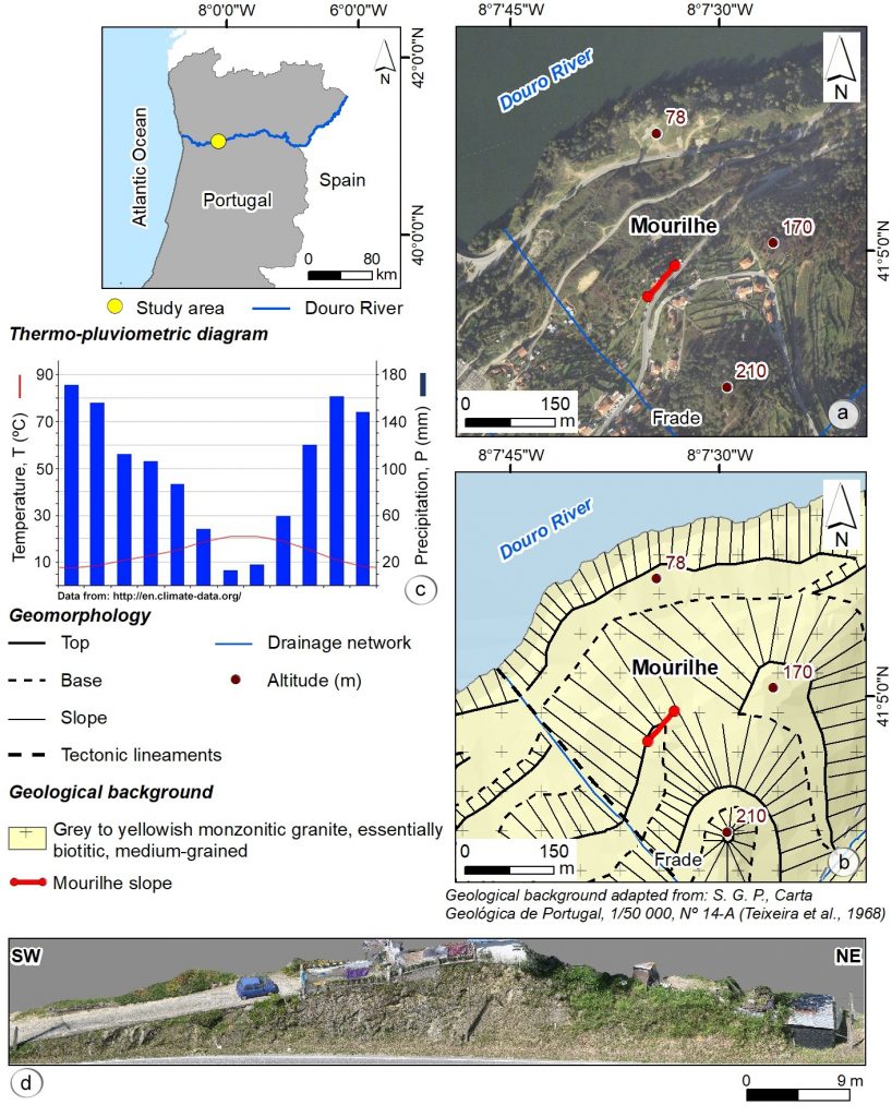
Figure 4: Mourilhe road slope setting (Cinfães, N Portugal): (a) Geographic location (Google Earth Pro); (b) Geomorphological and geological background; (c) Thermo-pluviometric diagram; (d) General view of the slope.
Table 1 summarises the most important in situ geological and geotechnical parameters collected and analysed from the Mourilhe rock slope.
Table 1: Summary of the basic geotechnical parameters for the Mourilhe rock slope.

The rock mass has dominantly a poor to moderate geomechanical quality based on SMR, RMR and GSI schemes (Figure 5c). The slope was classified (RHRSM2 and SQI) as unstable, with a moderate to high susceptibility to and a moderate hazard of rockfall (Figure 5d).

Figure 5: Geotechnical and geomechanical assessment: geotechnical and geomechanical zoning (the dots mark the zoning units’ boundaries) and rock slope hazard zoning based on rockfall rating system and slope quality index. (a) Scanline and geological cross-section; (b) Geotechnical zoning; (c) Geomechanical zoning; (d) Rockfall hazard features; (e) Several aspects of the rocky slope instability.
The geomechanical parameters adopted for the stabilisation evaluation are synthesised in Figure 6. The evaluation of the slope stability was carried out with Slide and RS2 software (Rocscience). For these analyses, two geometrically accurate cross-sections (P1 and P2) were selected from the 3D slope model obtained from UAV aerial surveys (Figures 6a and 6d). Based on the geomechanical characterisation resulting from the fieldwork developed, equivalent values of the resistance parameters, φ and c, corresponding to the Mohr-Coulomb yield criterion, were determined (Figure 6a). Figure 6b shows the minimum safety factor calculated with Slide software for the vertical slope cross-section profile P2. It also presents the Strength Reduction Factor (SRF) critical value obtained with the RS2 software, using the Shear Strength Reduction (SSR) functionality. The values are similar in both calculations, and a reasonable safety reserve was identified concerning the global instability of the slope. An engineering protection solution was proposed after the geological, geotechnical and geomechanical studies and implemented. The protection solution is composed of high tensile wire mesh connected to steel profiles on the slope base, and a gutter was also installed near the base of the slope (Figure 6c).
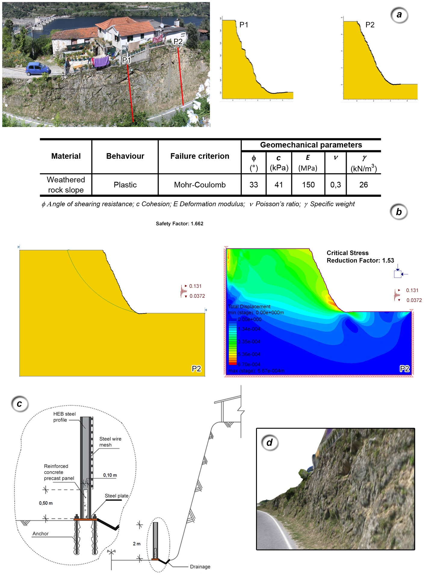
Figure 6: Geotechnical modelling and protection solution design adopted for Mourilhe road slope. (a) Profiles P1 and P2 and the geomechanical parameters used; (b) Minimum safety factor and critical SRC for P2 (Slide and RS2 software from Rocsience); (c) Schematic cross-section with the proposed protection features; (d) 3D slope model resulting from UAV aerial surveys.
Luriz cemetery case study
This case study is related to hydrogeotechnical issues found in the final stage of constructing a new cemetery located in Luriz, Valongo city (NW Portugal), particularly the severe groundwater inflow in some graves that prevented their use (details in Chaminé et al., 2016). No burials were permitted until this problem was solved. Due to Portuguese legal restrictions for cemeteries, it is forbidden to install permanent or seasonal dewatering non-gravitic systems and solutions, which means that natural drainage must prevail (Nascimento and Trabulo, 2008). That is mainly because of potential geoenvironmental issues, particularly due to the discharge of hazardous substances and non-hazardous chemical and biological pollutants to groundwater (Dent et al., 2004). The Luriz cemetery occupies an approximate area of 5000 m2. It is grounded in organic soil that overlays a highly weathered (W4-5) to residual soil (W6) of dark shale, covering the metasedimentary bedrock. The dominant regional fracture network is NNW-SSE to NW-SE and NE-SW sets. The valley of the Ferreira River is subordinated to the mentioned fracturing systems. The bedrock consists of slightly weathered slaty and clayey fine-grained shales (W1-2), dark grey to black, compact, with well-marked schistosity (N160°E; 70°NE). Milky quartz veins crosscut the shales. Joints were also recorded, with a sub-perpendicular orientation to regional schistosity (N60°E; sub-vertical). Joints are usually close to open (<0.5 mm), slightly rough (R1-2), close to very close spacing (F4-5: 6-15 cm), continuous, poorly filled (silty-clayey), and damp.
The Luriz cemetery is partly located on ground where the water table is at the subsurface, at a depth of less than 3.5 m, with minor seasonal variations. The topographic surface is partly flooded since a local stream cannot contain periods of intense precipitation. Moreover, the bedrock provides some level of imperviousness related to its silty-clay nature. Precipitation is, in general, profuse, presenting an uneven distribution throughout the year. There is a water deficit from June to September, particularly in July and August. The average annual precipitation is around 1240 mm/year, reaching circa 180 mm in the wettest month (December) and 20 mm in the driest month (July). The actual evapotranspiration is about 50% of the precipitation, and the direct groundwater recharge is about 10–15%. Figure 7 shows that the local hydrographic network drains into the Ferreira River, located SW of the cemetery. One of these streams crosses the cemetery area diagonally with a direct impact on its use. During the cemetery construction, this stream was diverted to a ditch located next to its NE-SW limit.
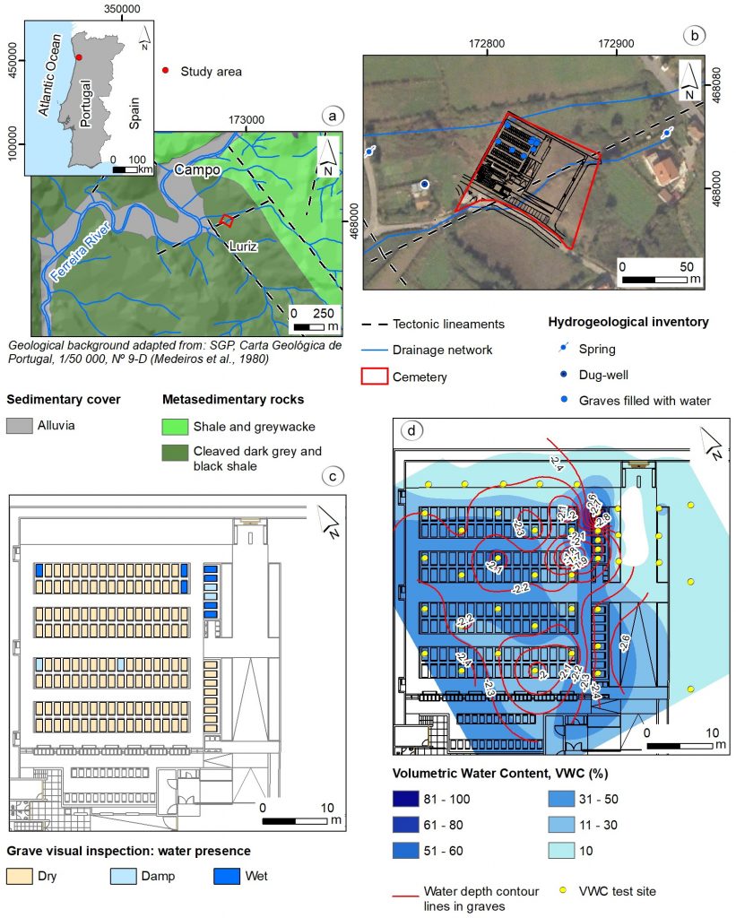
Figure 7: Luriz cemetery (Valongo, NW Portugal): (a), (b) geological and geographical setting (Google Earth Pro from 2005); (c) visual inspection and hydrological inventory of the graves (cemetery layout in 2010); (d) volumetric water content (%) mapped on the ground (adapted from Chaminé et al., 2016).
Several studies have been conducted to solve the inflow problem into the Luriz cemetery graves. The first one consisted of a hydrogeological inventory of the groundwater manifestations in the cemetery’s vicinity and several cemetery graves. Twelve points were inventoried, including one well, two springs and nine graves. Each point was assigned an inventory number, and several characteristics were recorded. For the well, springs and the graves that contained water, in situ physicochemical properties of water were recorded: temperature, pH, and electrical conductivity (EC, μS/cm). The degree of soil moisture and the bedrock’s depth for the remaining graves were evaluated whenever possible. The wells and springs’ pH values are lower (ca. 5) than those of the cemetery graves (7–9). As for EC, the values are in the range 250–700 μS/cm.
A visual inspection of all the cemetery graves was made to check the water level at a later stage. It was noticed that most of them were dry, except Graves 1, 2, 6, 15, 16 and 143, which contained water, and Graves 75 and 147, which were wet. A more accurate definition of the water content at the soil moisture in the graves’ base and some locations on the cemetery’s surface was obtained by a capacitance probe (Theta Probe; Delta-T Devices, Cambridge), which assesses the volumetric water content of soil moisture. Based on these data, a map of isolines of volumetric water content (%) was elaborated, which verified that the highest level of water content was clustered in the zone of Graves 1 to 6, especially in Graves 1, 2 and 6. Besides, based on that data, the groundwater flow seems to be from NE to SW. That agrees with the main joint sets orientation and the stream that crosses transversely the cemetery site, grounded, and redirected.
To better understand the in situ geotechnical site conditions, two trenches were excavated with a backhoe: Trench 1 (T1), 45 m long and with a depth of 1.80–2.50 m, and Trench 2 (T2), 12 m long (see Figure 8a). Both trenches have reached the metasedimentary bedrock. The analysis of the ground profile in T1 allowed the establishment of the following horizons: a superficial horizon of organic soil; a grave landfill level consisting of loamy soils, with heterometric lithic-supported schists and greywackes, with a silty-clayey matrix and a yellowish-brown tone; a lower level corresponding to the dark grey shale bedrock. Along with T1, the water content presence was mapped, which verified the presence of alternating dry and damp/wet areas, highlighting the trench’s edges, where there is a clear presence of water. Along almost the total length of T2, the outcropped bedrock was recorded. It is important to note that no precipitation occurred in a couple of weeks before developing the fieldwork.
All the gathered data permitted us to conceptualise the groundwater circulation in the cemetery site. Figure 8a highlights the structural bedrock constraints, namely schistosity trending to NNW-SSE (and dipping to 70ºNE), and joint sets system with ENE-WSW orientation and sub-vertical dip. Figure 8b presents a hydrogeological cross-section that illustrates the geo-hydraulic conditions and the grave excavation positioning with water presence (Graves 1–6, 15, 16, 143). The graves acted as natural discharge points and were excavated in the bedrock and/or in the residual soil. Also, the remaining graves are positioned to a reasonable depth of the bedrock, set up in the cemetery landfill and/or in the slaty residual soil and with no water presence. A final remark is that the entire cemetery is bordered by a concrete wall founded in the bedrock. This infrastructure may, in part, contribute to confinement and disturbance of the underground hydraulic circuit.
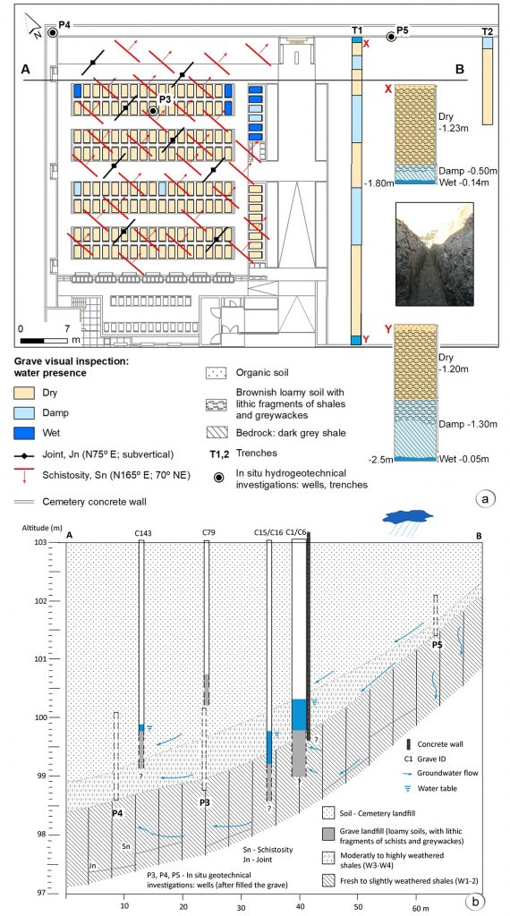
Figure 8: Inputs to the conceptual hydrogeological site model (adapted from Chaminé et al., 2016): (a) schematic mapping of the structural geology constraints of the rock mass and hydrogeotechnical logs (X, Y) and trenches mapped (T1, T2); (b) Interpretative hydrogeological cross-section (AB) with conceptual site model.
Concluding Remarks
GIS mapping is one of the techniques currently in use to support geotechnical studies such as slope stability analyses or hydrogeotechnical assessments. Additionally, the hydrogeological site conditions are of keen importance in any geotechnical study. The main advantage of using engineering geoscience mapping is that it is a simple and effective way to communicate geological, hydrogeological, geotechnical, geomechanical, and geoenvironmental information. Several methods and techniques are currently being used to assess slope stability (e.g., Romana et al., 2015; Wyllie, 2018). Rock slope instabilities constitute a significant hazard for human activities and ecosystems, frequently affecting socioeconomic losses, property damages and maintenance costs, as well as for injuries and or casualties (e.g., Pantelidis, 2009; Pinheiro et al., 2015). The combined geotechnical and geomechanical studies based on mapping, the rock classification schemes and indexes prove to be efficient tools in supporting the geotechnical evaluation and engineering design.
Finally, interdisciplinary methodology provides a crucial view to better understanding the studied sites’ potential hazards. That approach is decisive to a balanced and safe solution in sustainable design with nature and geo-hazards (McHarg, 1992; González de Vallejo, 2012) and contributing to building a comprehensive site model based on reliable data and incorporating inherent ground variability and uncertainty (e.g., Griffiths, 2014; Chaminé et al., 2015; Fookes et al., 2015).
In summary, the geotechnical engineer John Neville Hutchinson stated an inspiring thought: ‘To appraise a site properly, identifying the nature, structure and boundaries of its component materials, the locations and nature of discontinuities present and any relevant changes in conditions, and thence to establish a sufficiently correct geological model to form the basis of the geotechnical model for design of the proposed works, is undoubtedly one of the more demanding tasks that we face.’ (Hutchinson, 2001:7). Last but not least, as highlighted by the engineering geologist Peter Fookes, that approach shall be rigorous straightforward, i.e., the field geologists or engineers shall use the KISS principle: ‘Keep It Simple, Stupid!’ (Fookes et al., 2015:8).
Acknowledgements
Some projects partially supported this study: LABCARGA|ISEP re-equipment program (IPP-ISEP| PAD’2007/08), and Centre GeoBioTec|UA (UID/GEO/04035/2020). We are grateful to J. Teixeira and J. Espinha Marques for the fieldwork inputs on the Luriz site. Our thanks to Cinfães municipality and Valongo municipality for their kind support in some stages of fieldwork. Special thanks are due to Nicole Devy-Vareta and Rafael Fernández-Rubio for kindly reviewing the French and Spanish version of the abstract, respectively. Our appreciation to our colleague I. Fernandes and reviewers for their valuable comments that helped improve the manuscript focus. The paper is dedicated to Professor Luís Ribeiro e Sousa, an outstanding Portuguese geotechnical engineer who promotes high standards in rock mechanics and rock engineering research, teaching, and practice.
References
Barton, N. & Quadros, E. 2015. Anisotropy is everywhere, to see, to measure and to model. Rock Mechanics and Rock Engineering, 48. 1323–1339. DOI: 10.1007/s00603-014-0632-7
Bieniawski, Z.T. 1989. Engineering Rock Mass Classifications: A Complete Manual for Engineers and Geologists in Mining, Civil, and Petroleum Engineering. Interscience, Wiley: New York
Chaminé, H.I., Afonso, M.J., Carvalho, J.M., Teixeira, J. & Espinha Marques, J. 2016. Considerações hidrológicas sobre o novo cemitério de Luriz, Valongo (NW de Portugal) (Hydrological remarks about the new graveyard of Luriz, Valongo (NW Portugal)). In Chaminé, H.I., Afonso, M.J., Galiza, A.C. (eds.), Eduardo Gomes: Engenheiro, Docente, Empreendedor – Uma Homenagem, Porto, Portugal. (pp. 133–142) Colecção LABCARGA-Geo|2, Instituto Superior de Engenharia do Porto, Porto.
Chaminé, H.I., Afonso, M.J., Ramos, L. & Pinheiro, R. 2015. Scanline sampling techniques for rock engineering surveys: insights from intrinsic geologic variability and uncertainty. In Giordan, D., Thuro, K., Carranza-Torres, C., Wu, F., Marinos, P., Delgado, C. (eds.), Engineering Geology for Society and Territory – Applied Geology for Major Engineering Projects, IAEG, Springer, 6.357-361. DOI 10.1007/978-3-319-09060-3_61
Chaminé, H.I., Afonso, M.J., Teixeira, J., Ramos, L., Fonseca, L., Pinheiro, R., Galiza, A.C. 2013. Using engineering geosciences mapping and GIS-based tools for georesources management: Lessons learned from rock quarrying. European Geologist, 36. 27-33.
Dearman, W.R. 1991. Engineering Geological Mapping. Butterworth-Heinemann: Oxford
Dent, B.B., Forbes, S.L. & Stuart, B.H. 2004. Review of human decomposition processes in soil. Environmental Geology, 45. 576–585. DOI_ 10.1007/s00254-003-0913-z
Fookes, P., Pettifer, G. & Waltham, T. 2015. Geomodels in Engineering Geology: An Introduction. Whittles Publishing: Dunbeath
González de Vallejo, L.I. 2012. Design with geo-hazards: an integrated approach from engineering geological methods. Soils and Rocks, International Journal of Geotechnical and Geoenvironmental Engineering 35(1).1–28. http://www.abms.com.br/links/soilsandrocks/solos-e-rochas-vol35-n1.pdf
Griffiths, J.S. (ed.) 2002. Mapping in Engineering Geology. Key Issues in Earth Sciences Series, Vol. 1. The Geological Society of London: London
Griffiths, J.S. 2014. Feet on the ground: engineering geology past, present and future. Quarterly Journal of Engineering Geology and Hydrogeology, 47(2). 116-143. DOI 10.1144/qjegh2013-087
Griffiths, J.S. & Stokes, M. 2008. Engineering geomorphological input to ground models: an approach based on earth systems. Quarterly Journal of Engineering Geology and Hydrogeology, 41.73-91. DOI 10.1144/1470-9236/07-010
Gustafson, G. 2012. Hydrogeology for Rock Engineers. BeFo and ISRM Edition: Stockholm
Hoek, E., Carter, T.G. & Diederichs, M.S. 2013. Quantification of the geological strength index chart. In Pyrak-Nolte, L.J. (ed.), Proceedings of the 47th US Rock Mechanics and Geomechanics Symposium, ARMA 13–672, San Francisco, p. 1–8
Hutchinson, J.N. 2001. Reading the ground: morphology and geology in site appraisal. Quarterly Journal of Engineering Geology and Hydrogeology, 34.75–50. DOI 10.1144/qjegh.34.1.7
McHarg, I.L. 1992. Design with Nature. 25th anniversary edition. Wiley Series in Sustainable Design, John Wiley & Sons: New York
Nascimento, E., Trabulo, M. 2008. Cemitérios 3.ª edição (Cemetaries, 3rd ed.). Almedina: Coimbra
Norbury, D. 2021. Ground models: a brief overview. Quarterly Journal of Engineering Geology and Hydrogeology, 54(2). DOI: 10.1144/qjegh2020-018
Pantelidis, L. 2009. Rock slope stability assessment through rock mass classification systems. International Journal of Rock Mechanics and Mining Sciences, 46, 2. 315–325. DOI: 10.1016/j.ijrmms.2008.06.003
Pinheiro, M., Sanches, S., Miranda, T., Neves, A., Tinoco, J., Ferreira, A. & Correia, A.G. 2015. A new empirical system for rock slope stability analysis in exploitation stage. International Journal of Rock Mechanics and Mining Sciences, 76. 182-191. DOI: 10.1016/j.ijrmms.2015.03.015
Priest, S.D. 1993. Discontinuity Analysis for Rock Engineering. Chapman and Hall: London.
Romana, M., Tomás, R. & Serón, J.B. 2015. Slope Mass Rating (SMR) geomechanics classification: thirty years review. In Hadjigeorgiou, J., Archibald, J. (eds.), Proceedings of the 13th International Symposium on Rock Mechanics, ISRM, Quebec, p. 1-9.
Wyllie, D.C. 2018. Rock Slope Engineering: Civil Applications. Fifth Edition. CRC Press, Taylor & Francis Group: Boca Raton.
This article has been published in European Geologist Journal 51 – Geotechnics – Building sustainable foundations
Read here the full issue:
